Raspberry Pi Powered Flying Geese Clock
LEDs programmed with Python and controlled through MQTT bring this traditional quilt pattern to life
The clock consists of a quilt top mounted over a cardboard frame embedded with LEDs. The lights are connected to a Raspberry Pi Zero and shine through the fabric to indicate the hour, and bathe the wall in red to give a vague notion of minutes past.
As well as being a time piece, the quilt includes various timers and ambient settings, the controls for which I was determined would be more instantaneous than with my previous projects. Inspired by Kevin McAleer and others I decided I would treat this quilt like a robot and control it via MQTT, the lightweight, publish-subscribe network protocol.
Construction
I made the quilt by following a simple ‘Circle of Geese’ foundation paper piecing pattern I found on Etsy. With this method, fabric is sewn onto a paper template one piece at a time to create a precise final design. Once complete the paper is removed leaving the quilt top behind.
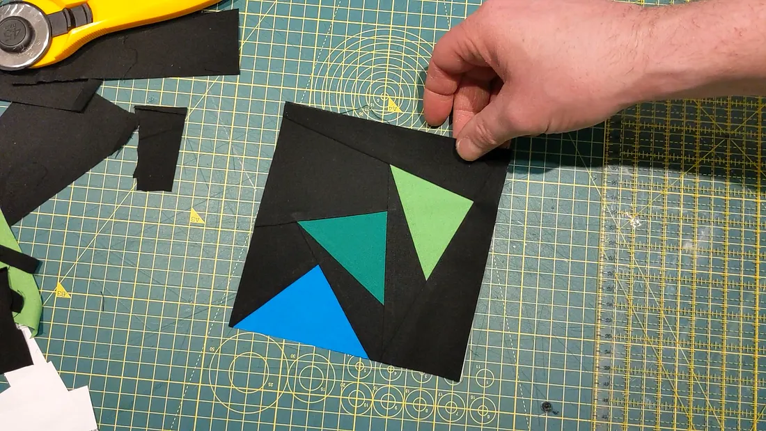
There are many inspirational modern creations made this way, such as the ‘The Heart of a Lion’ pattern shown below. Modern paper piecing designs like this are reminiscent of low poly graphic art made with Photoshop, only with fabric and three dimensions.

Light diffusion
I was really pleased with how each of the four sections came together and part of me wanted to light the whole thing in a way that would reveal the hidden detail of the piecing and seam allowances. However, without each of the ‘Geese’ illuminated separately it would be hard to show the 12 hours of a clock face.
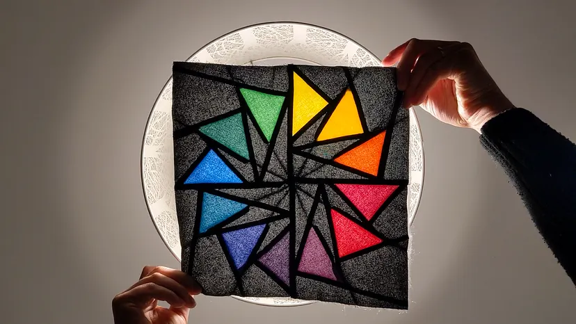
Quilt wadding is a good material for diffusing the light from the LEDs. I used a double layer to ensure individual pixels would not be seen as spots through the fabric. I then stitched six lines through the centre before going around each triangle in the hope that this would create a barrier between the edges.
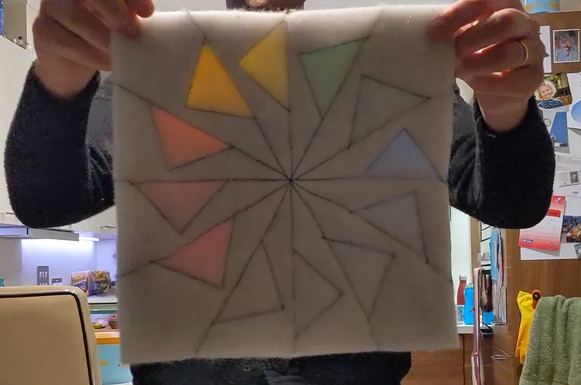
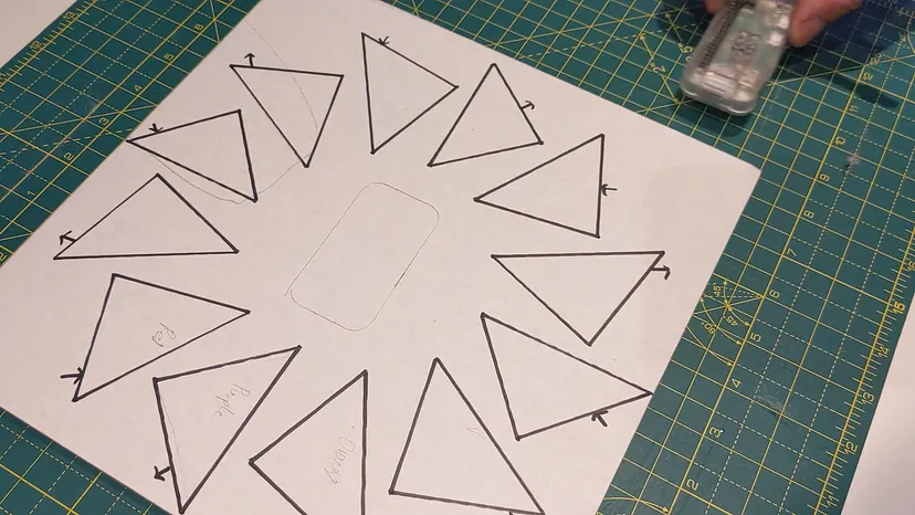
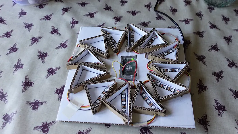
Once the quilt top was complete with binding on the edges, I set about making a frame. The quilt top measures 30cm × 30cm so I cut a square piece of cardboard slightly smaller than this and marked out where the triangles would be. To help diffuse the light more evenly I planned to leave a small gap between the quilt top and the cardboard where the LEDs would be mounted. I would use 15mm strips of cardboard to create this elevation.
Raspberry Pi
The RGB WS2812B LEDs connect to a Raspberry Pi Zero and are controlled with a Python script. As with my previous projects I followed the user guides found on the Adafruit website to get configured with CircuitPython. I used a 5V power supply to power both the Pi and the lights.
In a bid to avoid soldering, I foolishly bought some connectors which snapped onto the LED strips on one side and the power and data wires on the other. I thought this would give the whole construction process a simple Lego-like feel, however I could never get them connected sufficiently enough to prevent a very obvious voltage drop. So, it was back to the soldering drawing board, which did in the end pay off.
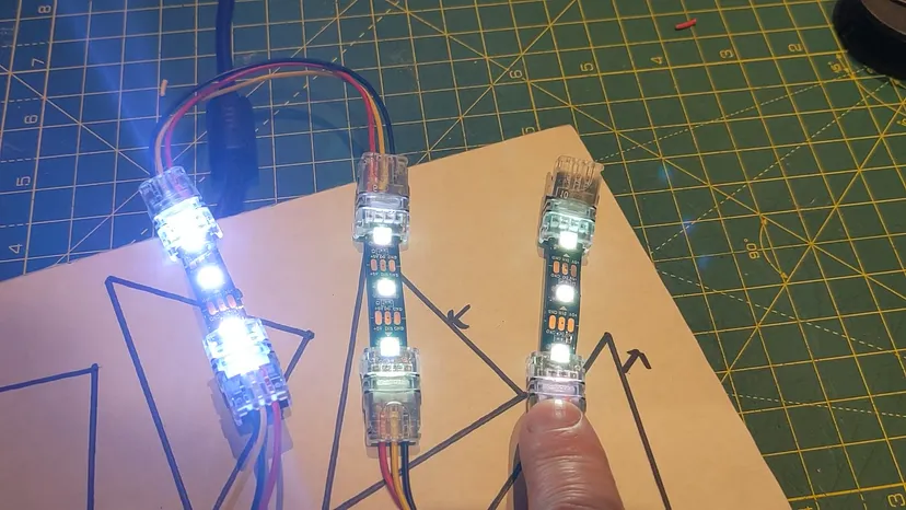
Each ‘hour’ on the clock is made of three LEDs and at 12 O’clock the whole face lights up like there’s been an accident at the Large Hadron Collider. Placing the quilt top casually over the lights gave an interesting effect, but without any clear separation between the hours.
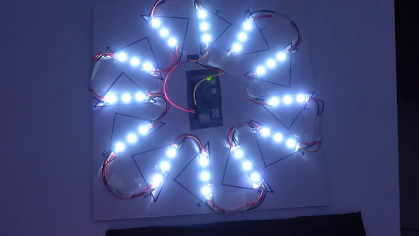
Once I had glued the strips on to create the elevation, the cardboard backing in itself began to look striking when lit, and although not perfect, the triangular geese did a good job of containing the light.
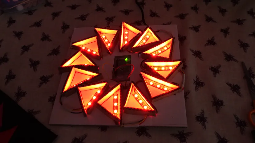
To show the minutes elapsed, 36 more LEDs form a circle on the back to bounce light off the wall — initially I intended to have groups of three lights for each five minute interval, but in the end I awkwardly used them all to create a progress bar of sorts. In the Python script, minutes past is expressed as a fraction of an hour and then multiplied by 36. E.g. at 30 minutes past (30/60ths of an hour) 18 of the lights shine red and the rest white; at 5 minutes to (55/60ths of an hour) only 3 white lights remain.
So this is what 8:25 looks like:
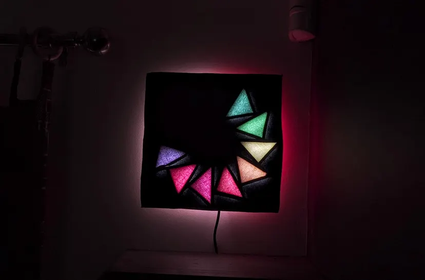
In hindsight, I wish I’d put more lights on and closer to the edges following the square outline, as the circle shape is lost. It’s a case of round peg, square quilt!
MQTT, Python and JavaScript blend
For the clock function, the Python script obtains the time from the internet and then changes the appropriate lights, and this is the program’s default behaviour. Other programs treat the quilt like a lamp and set various ambient backlit colours. The final programs function as egg timers with the front spinning like a real life loading screen.
There is a timer for soft boiled eggs which runs for 4 minutes and one for hard boil eggs which runs for 10. While the timer is running the green value descends from 255 to 0 and the red value does the reverse. A quick glance at the wall tells you roughly how far through cooking the eggs are. At half-way the light is equal parts red and green, otherwise known as orange, and once complete the wall glows green before the lights blink off.
The Raspberry Pi is configured as an MQTT broker with Mosquitto and as a client using the Paho MQTT Python library.
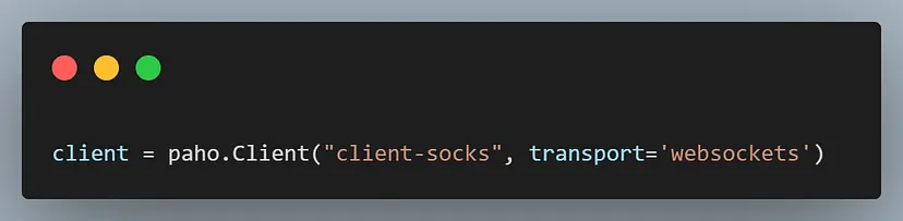
It also uses the Apache web server to host a simple HTML page with embedded JavaScript that creates an open WebSocket to the broker on the Pi. This can be loaded on any device on our network.
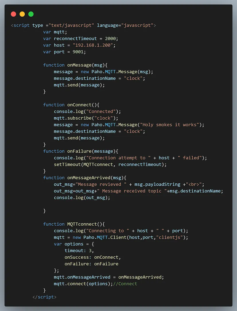
A user’s button press triggers a message to be published to the waiting Python script and the end result feels as instantaneous as a wall mounted light switch.
I used Jeremy Cook’s tutorial about Mosquitto and Steve’s Internet Guide about MQTT, Paho and WebSockets to get me started with the code and I look forward to building on this learning in future projects. One consideration is whether a Raspberry Pi Zero is in fact the best tool for the job. I used it because it was spare and I knew what I was doing with the Apache web server and obtaining the current time. Perhaps a Pico with a Wi-Fi module and real time clock would be the better approach. And perhaps it’s time I took a dive into the world of Node-RED and all its applications.
The follow-up clock using a Raspberry Pi Pico W, battery power, and a 3D cut mount board housing
You can see all the code for this project over on GitHub.
If this is your sort of thing and you’ve enjoyed reading about this project, please consider following me on Medium or subscribing to my YouTube Channel.