Striking Binary Clock with Raspberry Pi Pico W and Addressable RGB LEDs
A vibrant way to keep time and deepen understanding of the base 2 numbering system
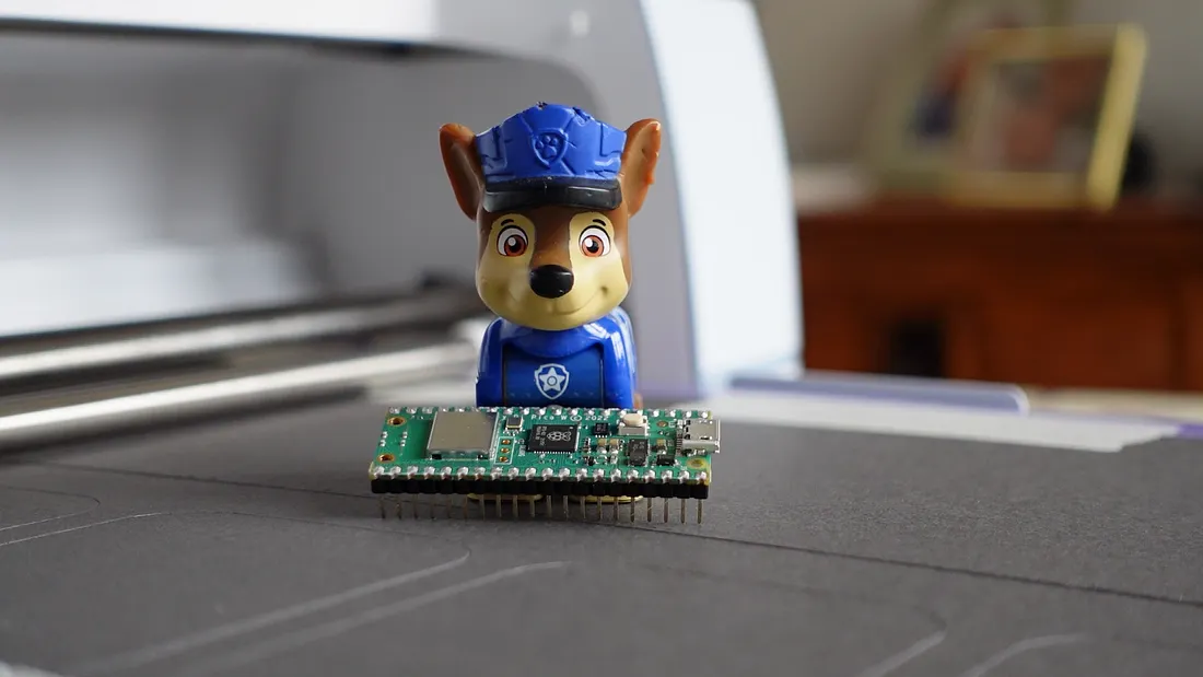
The binary clock is powered by the Raspberry Pi Pico W and programmed using MicroPython.
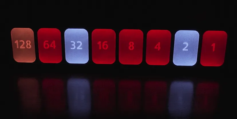
Addressable LEDs illuminate eight binary bits in different combinations to display either the time or the status of various timers.
Purpose and design choices
I wanted to create a novelty clock for my classroom that serves as a decorative item and also functions as an educational tool to demonstrate how the base 2 numbering system works.
My technology and construction goals for the clock were threefold:
- Microcontroller over computer: Use a microcontroller instead of a full Raspberry Pi computer to simplify operation and eliminate boot-up time and shutdown issues.
- Cord-free and wireless-independent: Create a battery-powered device that doesn’t require a Wi-Fi network connection for use, and to avoid unsightly wires.
- Crafting and cutting machine: Make use of a cutting machine; I am inspired by the many ways people use 3D printing in projects, but I am drawn to making use of fabric, card and paper.
Understanding Binary and Decimal Number Systems
Most binary clocks use four bits to display decimal values up to 15, with separate columns for hours, minutes, and seconds. However, this can make it confusing to understand the connection between binary (base 2) and decimal (base 10) systems.
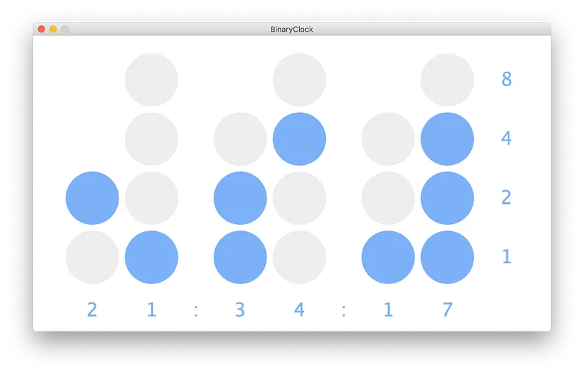
Base 2 (binary) and base 10 (decimal) are different ways of representing numbers.
In base 2, there are only two possible digits: 0 and 1. Each digit represents a power of 2, starting with 2⁰ = 1, then 2¹ = 2, 2² = 4, 2³ = 8, and so on. So in binary, the number 34 would be represented as 100010, which means:
1 × 2⁵ (32) + 0 × 2⁴ + 0 × 2³ + 0 × 2² + 1 × 2¹ (2) + 0 × 2⁰ = 34
In base 10, there are 10 possible digits: 0 through 9. Each digit represents a power of 10, starting with 10⁰ = 1, then 10¹ = 10, 10² = 100, 10³ = 1000, and so on. So in decimal, the number 34 is represented as 34, which means:
3 × 10¹ (30) + 4 × 10⁰ (4) = 34
To ensure accurate display of binary values up to 60 minutes, I designed the clock to utilise a full 6 bits. Additionally, I added two extra bits to enable counters up to 256 when the clock is not in use.
Building and Illuminating the Clock Housing with NeoPixels
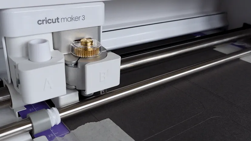
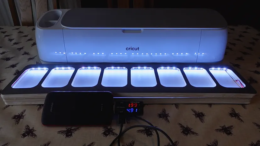
The clock housing is built from layers of mount board, cut with a Cricut machine and then glued together. Rectangles house each of the eight bits, with a top layer of slightly smaller rectangles cut with rounded corners. This top piece allows for the LEDs to be slightly recessed for more even light distribution.
To illuminate each bit, I used 8 NeoPixels (WS2812 RGB LEDs) arranged in a row of four at the top and four at the bottom.
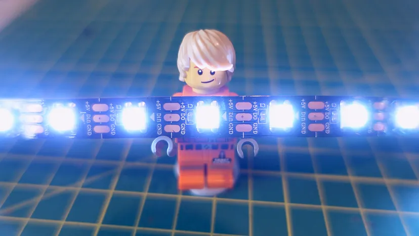
Adafruit’s Uberguide specifies a maximum current draw of 60 milliamps per LED, but in my experience with LED projects, the actual current draw has been lower. In this clock project, the 64 LEDs drew around 2 amps at full brightness, which translates to approximately 30 milliamps per LED. This was within the 2-amp rating of the battery I planned to use, making it an ideal choice for the project.
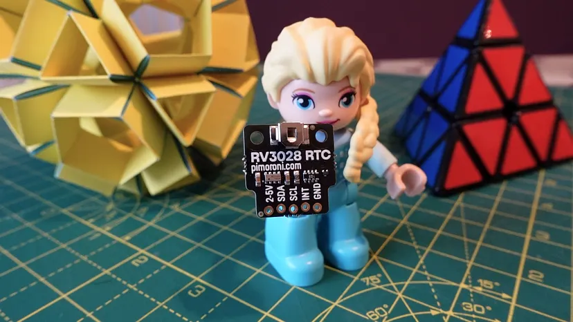
Since the Raspberry Pi Pico W lacks its own clock and the project won’t be connected to Wi-Fi, I opted to use an external clock module. I chose the Pimoroni RV3028 Real-Time Clock Breakout, which includes a battery and a promise of five years of accurate timekeeping.
To power both the Pico and the LEDs from a single source, I used a female USB breakout board with a common ground connection and to prevent power surges from damaging the first LED, I added a capacitor to the circuit, as recommended by Adafruit.
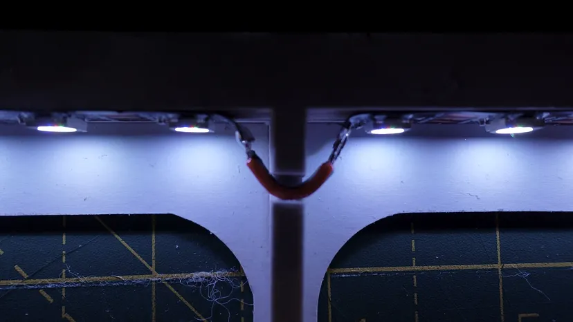
The 64 LEDs loop along the bottom and then back along the top, starting and ending in the first bit. Irritatingly, I miscalculated the width of the rectangles, which meant that I needed to cut the LED into strips of eight then re-connect the terminals with small lengths of wire.
Diffusing Light with Lutradur Fabric
To diffuse the light, I used a fabric called Lutradur, a spunbonded polyester fabric often used in craft projects involving light. I used the Cricut machine to cut precise Lutradur rectangles to fit the gaps, which were then affixed to paper rectangles featuring stencilled cut-outs of the required numbers.

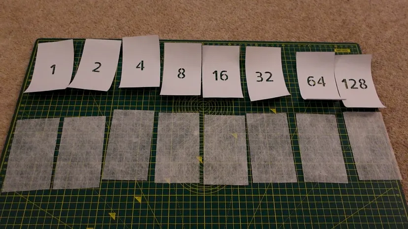
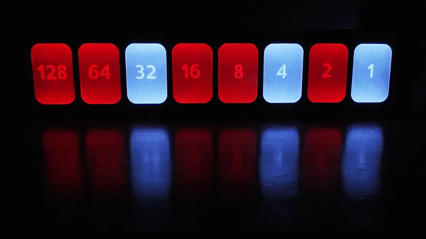
The outcome is a subtly illuminated display of the numbers that appear almost concealed when unlit.
Programming the Clock
The full code for this project can be found in the GitHub repository, but essentially there were four main steps involved in coding this project:
- Installing MicroPython and Neopixel libraries
- Configuring the Pico W to operate as a wireless access point
- Setting then getting the time from the Real Time Clock Module
- Coding a single
main.pyfile to bring it all together
MicroPython and NeoPixels
I followed the tutorials on the Raspberry Pi website to install MicroPython, and followed the guidance on Blaz-R’s GitHub repository to get up and running with the Neopixel library.
Setting the Pico as a Wireless Access Point
Michael Horne’s post got me started with setting up the Pico as a webserver using a library called TinyWeb, which is like Flask, but for MicroPython. It required relatively little code to get the Pico W serving as its own access point. This will allow me to hang the clock up on the wall at work, and access it without needing it to be connected to the school network.
I, or a sneaky student, just needs to connect to the “Binary Clock” Wi-Fi network it creates, then visit 192.168.4.1 in the browser.
1# Define SSID and password for the access point2SSID = "Binary Clock"3PASSWORD = "123456789"4
5# Define an access point, name it and then make it active6ap = network.WLAN(network.AP_IF)7ap.config(essid=SSID, password=PASSWORD)8ap.active(True)9
10# Wait until it is active11while ap.active == False:12    pass13
14print("Access point active")15# Print out IP information16print(ap.ifconfig())
At the root of the site hosted on the Pico W a simple HTML page is served with links to other routes.
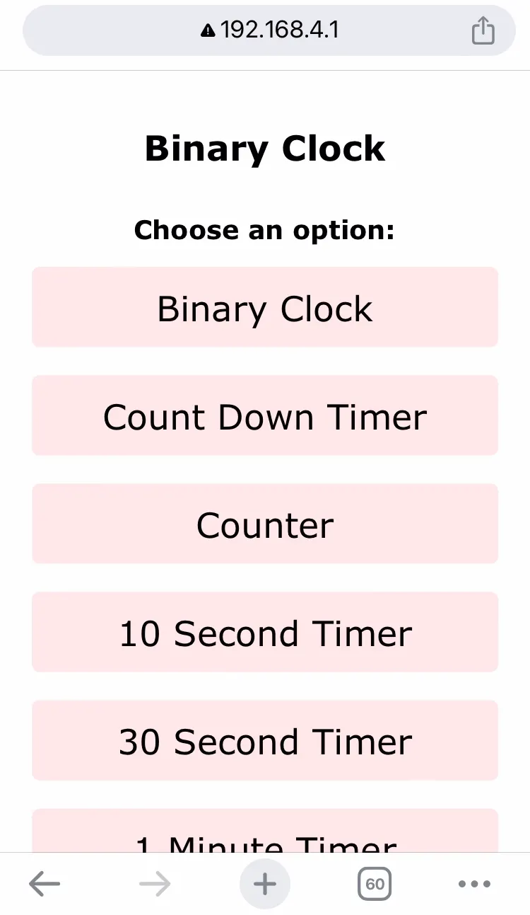
1@app.route('/')2async def index(request, response):3 # Start HTTP response with content-type text/html4 await response.start_html()5 # Send actual HTML page6 await response.send('''7 <!DOCTYPE html>8 <html>9 <head>10 <title>Binary Clock</title>11 </head>12 <body style="display:flex; flex-direction:column; justify-content:center; align-items:center; padding: 50px; font-family: verdana;">13 <h1 style="font-size: 4rem;">Binary Clock</h1>14 <h2 style="font-size: 3rem;">Choose an option:</h2>15 <a href="/clock" style="margin-bottom: 50px; width:100%;"><button style="font-size:4rem; font-family: verdana; width:100%; height: 150px; background-color: #ffe6e6; color: black; border-radius: 15px;">Binary Clock</button></a>16 <a href="/timer" style="margin-bottom: 50px; width:100%;"><button style="font-size:4rem; font-family: verdana; width:100%; height: 150px; background-color: #ffe6e6; color: black; border-radius: 15px;">Count Down Timer</button></a>17 <a href="/stopwatch" style="margin-bottom: 50px; width:100%;"><button style="font-size:4rem; font-family: verdana; width:100%; height: 150px; background-color: #ffe6e6; color: black; border-radius: 15px;">Stopwatch</button></a>18 <a href="/10-second-timer" style="margin-bottom: 50px; width:100%;"><button style="font-size:4rem; font-family: verdana; width:100%; height: 150px; background-color: #ffe6e6; color: black; border-radius: 15px;">10 Second Timer</button></a>19 <a href="/30-second-timer" style="margin-bottom: 50px; width:100%;"><button style="font-size:4rem; font-family: verdana; width:100%; height: 150px; background-color: #ffe6e6; color: black; border-radius: 15px;">30 Second Timer</button></a>20 <a href="/1-minute-timer" style="margin-bottom: 50px; width:100%;"><button style="font-size:4rem; font-family: verdana; width:100%; height: 150px; background-color: #ffe6e6; color: black; border-radius: 15px;">1 Minute Timer</button></a>21 <a href="/2-minute-timer" style="margin-bottom: 50px; width:100%;"><button style="font-size:4rem; font-family: verdana; width:100%; height: 150px; background-color: #ffe6e6; color: black; border-radius: 15px;">2 Minute Timer</button></a>22 <a href="/3-minute-timer" style="margin-bottom: 50px; width:100%;"><button style="font-size:4rem; font-family: verdana; width:100%; height: 150px; background-color: #ffe6e6; color: black; border-radius: 15px;">3 Minute Timer</button></a>23 <a href="/4-minute-timer" style="margin-bottom: 50px; width:100%;"><button style="font-size:4rem; font-family: verdana; width:100%; height: 150px; background-color: #ffe6e6; color: black; border-radius: 15px;">4 Minute Timer</button></a>24 <a href="/off" style="margin-bottom: 50px; width:100%;"><button style="font-size:4rem; font-family: verdana; width:100%; height: 150px; background-color: #ff6666; color: black; border-radius: 15px;">Stop</button></a>25 </body>26 </html>27 ''')28 print("home")Each route triggers a back button to be displayed and the OPTION global variable to be changed.
1@app.route('/clock')2async def index(request, response):3 global OPTION4 # Start HTTP response with content-type text/html5 await response.start_html()6 # Send actual HTML page7 await response.send('''8 <!DOCTYPE html>9 <html>10 <head>11 <title>Binary Clock</title>12 </head>13 <body style="display:flex; flex-direction:column; justify-content:center; align-items:center; padding: 50px; font-family: verdana;">14 <a href="/" style="margin-bottom: 50px; width:100%;"><button style="font-size:4rem; font-family: verdana; width:100%; height: 150px; background-color: #ffe6e6; color: black; border-radius: 15px;">Home</button></a>15 </body>16 </html>17 ''')18 OPTION = 119 print(OPTION)20 print("Clock Mode")A thread elsewhere in the code listens out for this OPTION variable change and runs the appropriate light function.
1def options():2 while True:3 time.sleep(2)4 if OPTION == 0:5 turnOff()6 elif OPTION == 1:7 clock()8 elif OPTION == 2:9 stopwatch()10 elif OPTION in range(3, 10):11 times = [255, 10, 30, 60, 120, 180, 240]12 timer(times[OPTION - 3])13 else:14 pass15 print(OPTION)Setting and Getting the time
I used the libraries provided by Core Electronics to get up and running with the Real Time Clock module. With their Makerverse_RV3028 library installed, it was straight-forward to get the clock configured, again with relatively few lines of code:
1def set_clock():2    time = {}3    time['hour'] = 104    time['min'] = 555    time['sec'] = 06    # AM/PM indicator optional7    # If omitted, time is assumed to be in 24-hr format8    time['ampm'] = 'PM'  # or 'PM'9    rtc.setTime(time)10    # rtc.setDate(date)11
12# Uncomment the function call below to set the time with the above values13# set_clock()14
15# Getting current hour and minute from RTC16hour = rtc.getTime()[0]17mins = rtc.getTime()[1]18sec = rtc.getTime()[2]19print("hour: ", hour, " mins: ", mins, " secs: ", sec)
Operation
When the clock is running, the 8 bits switch between displaying the hour and minutes. The hour requires a maximum of 4 bits, with the binary representation of 12 o’clock being 1100. The minutes require a maximum of 6 bits, with the binary representation of 59 minutes being 111011. To differentiate between which is being displayed, the 128 bit glows orange when the minutes are being shown, and when the clock is displaying the hour, both the 128 and 64 bits glow orange.
When the clock strikes the hour, a cuckoo variable is set to true, which tells the script to run a rainbow sequence.
I also programmed various timers. They are mesmerising to watch and over time you get a good sense of what is happening with the underlying place value of the base 2 numbering system. It is fun to watch the white bit travel to the left as number increases.
I programmed two separate functions to count up to and down from 256, only to realise that I only swapped the colour counting up — the countdown effectively counts up in red. Perhaps there is scope in future to use this clock as a tool to teach about signed bits, twos-compliment numbers or even binary shifts.
What the FFFFFF? The companion follow-up exploring base 16 and full-spectrum RGB hex codes
To see the clock in action check out the video at the top of this post. If you want to see the code in more depth check out the GitHub repository.
If you’ve enjoyed reading this article and would like to see more of my projects please consider following here on Medium or subscribing to my YouTube Channel.